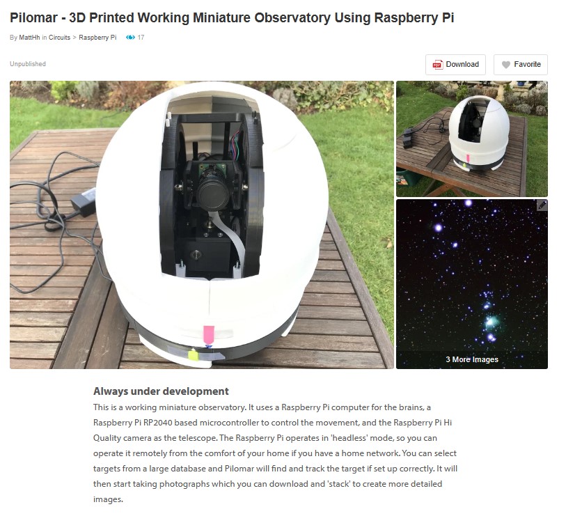
Been a while since I updated the blog so thought I’d post some updates on the project.
Peace and quiet, a TMC2209 story
The original project uses DRV8825 stepper motor drivers. These were the most commonly recommended drivers when I was first learning how to drive motors from a Raspberry Pi computer many years ago. They are simple, but they are noisy. If you are young you can hear them whine at higher frequencies! The signals they send to drive the motor coils are quite rough. So the project works, but I was uncomfortable with the noise especially when making large moves. You can reduce the loud mechanical noise by switching to microstepping, but the high pitched whine seemed to be a permanent feature.
A couple of people in the pilomar project group on Discord have recommended (and used) TMC2209 steppers instead. I am grateful to those alternative builds, it gave me some initial pointers to how to convert the project to use TMC2209s.
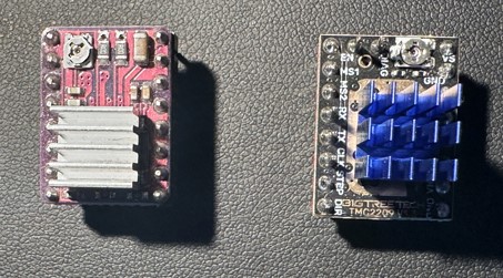
TMC2209 boards are a similar size to the DRV8825 and almost the same layout, but more sophisticated devices. They have more options and most importantly much smoother control signals!
One big advantage of the TMC2209 is that you can perform more functions AND more configuration tasks directly with the chip via a UART channel. The DRV8825 requires potentiometer adjustments and individual pin signals for everything. The TMC2209 does not which may make it easier for people to get the project up and running initially.
The challenge however was the UART communication! The original design uses Pimoroni Tiny RP2040/RP2350 microcontrollers and there are not enough pins available to add the extra serial communication lines needed. I needed more GPIO pins!
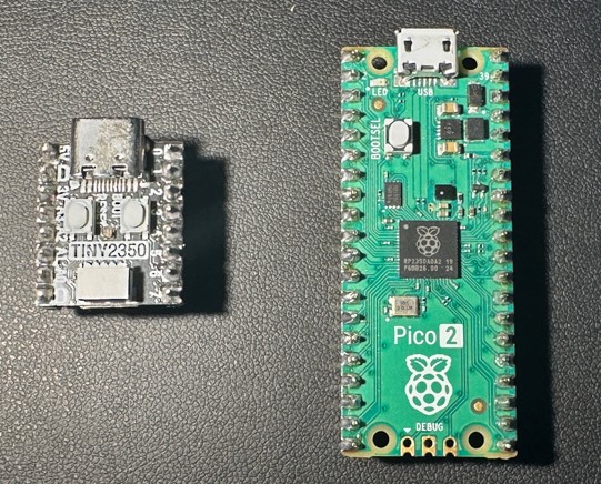
Very early in the project I had rejected the Raspberry Pi Pico RP2040 because it had proven too unreliable, with constant random resets that I could not eliminate. Now there is the Pico2 RP2350 available and after testing that the reliability is much better. So a large rewrite and restructure of the microcontroller was started. That took all of my spare time throughout 2025 – which explains why there have been no blog posts in 2025 either! Thanks go to Thomas Proffen too for kick starting the code restructuring for the microcontroller.
But after a lot of digging, learning, programming and testing I think I have a TMC2209 solution ready to roll back into the project. So far the results have been astounding, when I first ran the new solution I thought it was not working at all, the move commands resulted in no response from the telescope. After some panic I realised that it was in fact working but was so incredibly quiet and smooth that you couldn’t tell it was moving.
The TMC2209s have other tricks up their sleeve for future development, it looks like they can perform some actions even more autonomously than the DRV8825s, so there may be some more features to introduce still. But I’m really happy so far with the conversion. The telescope will finally sit and work on the desk in front of you and you’ll not notice!
I desperately need some clear calm nights now before the lighter nights arrive to really test the new board on some real observations. I want to verify that all the engineering changes are stable as much as possible before releasing the new
versions.
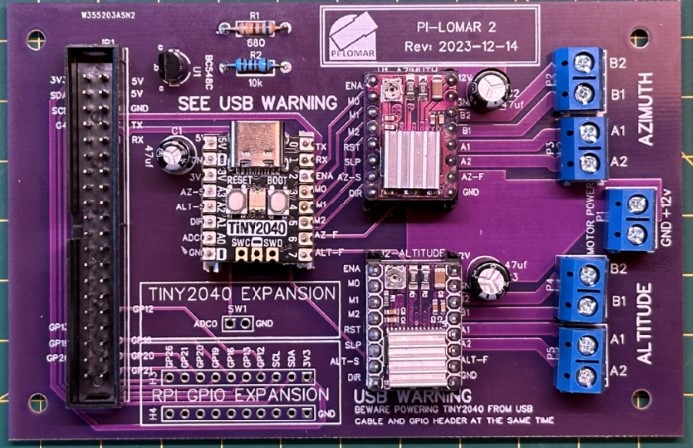
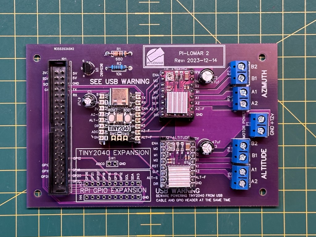
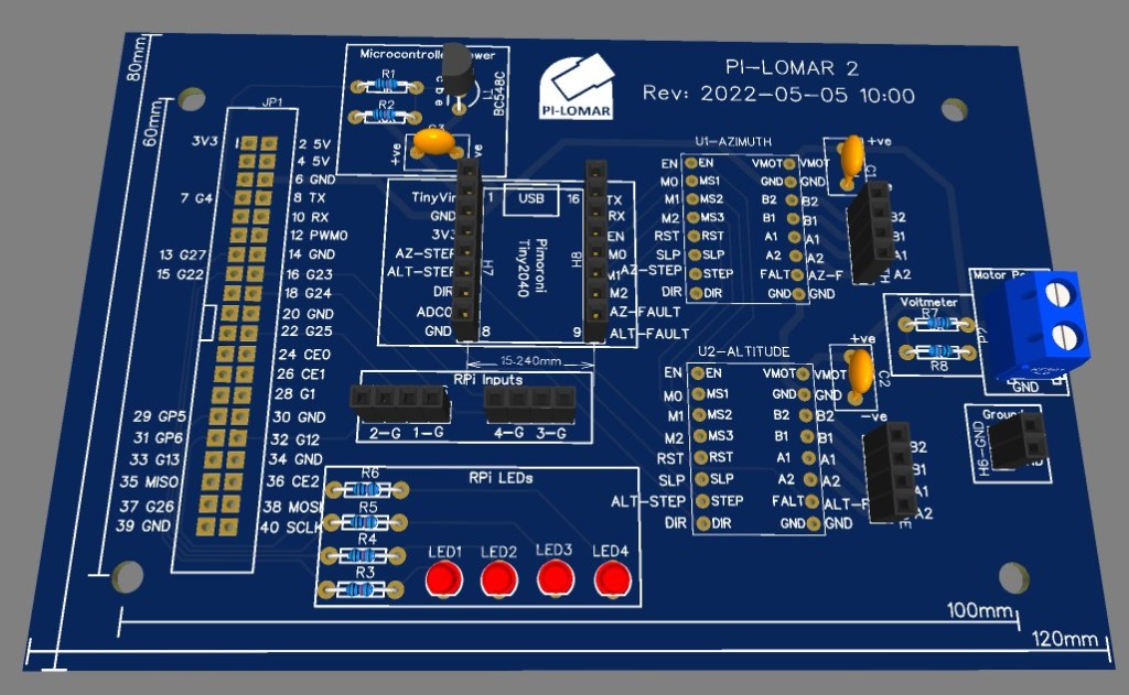
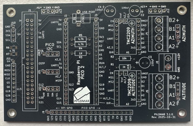
Some key points in the latest design
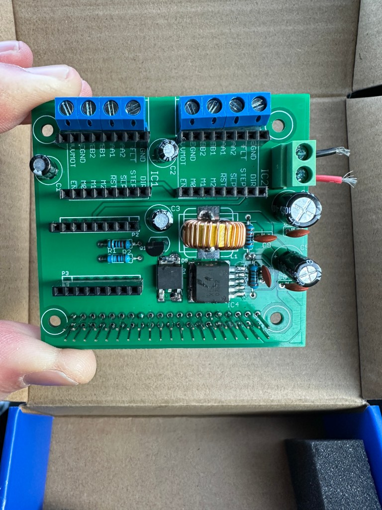
- The motor power monitoring is back. You can now measure the motor power voltage again. This is useful when troubleshooting and also when running from batteries.
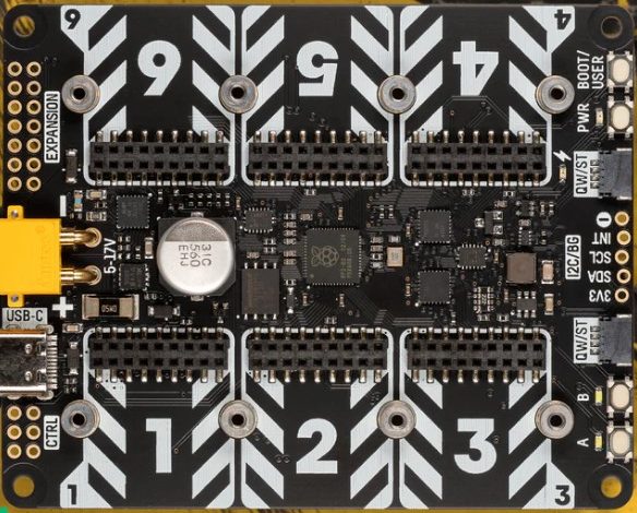
- The board now hosts a Raspberry Pi Pico 2 (RP2350) with more stability and more capacity.
- The DRV8825 sockets have been reworked to support the TMC2209 instead.
- There are more GPIO pins available on the Pico 2, so more have been exposed around the board edge for future expansion.
- 5V, 3V and 12V power points have been added to drive fans or other ‘light load’ accessories.
- The Pico2 I2C channel is made available to support position sensors and other addons.
- The ‘reset transistor’ circuit is eliminated for the microcontroller. This was to work around the lack of a reset pin on the Tiny2040. The new design supports a USB cable during operation better than before and the voltage supplied to the microcontroller is much higher now.
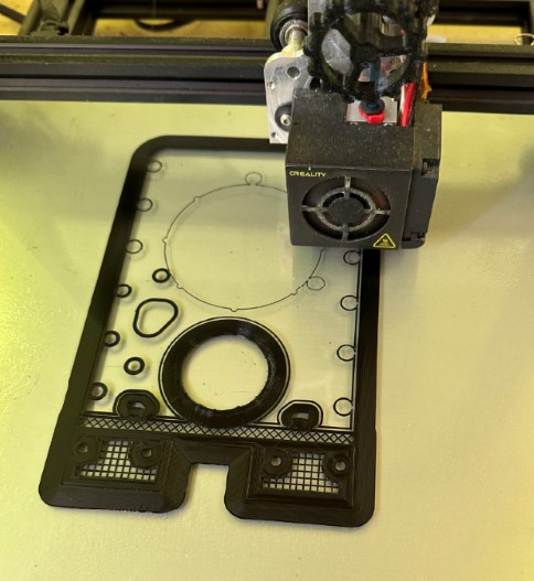
Another PCBWay order
By changing the microcontroller and stepper driver I had to revisit the PCB design again. I had already converted the project from EasyEDA to KiCAD in an earlier iteration, so it was time to re-open KiCAD and start adjusting the board design.
I had a new batch of the boards produced by PCBWay.com in China just before Christmas. The boards arrived as always remarkably quickly. I had them on my workbench less than a week after submitting the order. The speed of delivery alone is a great time saver in the project. I couldn’t make such a good quality board at home, and certainly couldn’t make a bunch of them at home as quickly as they can. These manufactured boards are also cheaper than the protoboards I was buying before! They look great, almost as if I know what I’m doing (I confess I’m still nervous!). I ordered the new ‘matt black’ finish on the PCBs and they look fantastic. I’ve used a different PCB color for each version of the design, but I think I’ll stick to the matt black from now on.
I always assumed I would be building the project with protoboard circuits, but I love the compactness and reliability of a professionally manufactured board so I’m not going back now. My current development route is :
- 1 – Breadboard : To learn what connections and components are needed.
- 2 – Protoboard : To test reliability and operation.
- 3 – Manufactured PCB : For reliable and compact deployment.
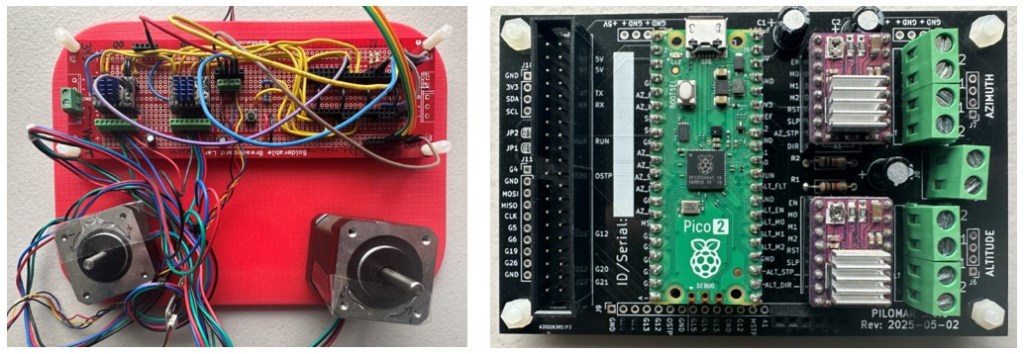
Having the boards made by PCBWay’s industrial process also increases the reliability of the circuits, I have less to worry about when assembling the final components. I typically order a batch of 5 or 10 boards so I have enough for my working builds plus a few spares for further experiments or repairs.
I usually only publish the gerber files in the GitHUB project but I see I can also create a kind of template order on the PCBWay website which would be fully configured and ready for anyone to place their own order too. That looks like a handy feature for people who are not confident in building or ordering manufactured PCBs.
I’m currently ordering unpopulated PCBs for development flexibility but I’m wondering about trying their more complete assembly service eventually too.
Testing went well, although I found one minor routing mistake in my KiCAD design. Luckily I was able to solve it with a couple of jumper wires, I didn’t even have to hack the board.
Application development
I’ve continued restructuring the code, but of course like all projects it’s also becoming larger as more features are added and more edge cases are handled by the code. So splitting into cleanly defined modules is sensible. Isolating the logic from the user interface more cleanly will also open the door to alternative UIs in the future.
Installation is still the same procedure as before, but there are now more files to transfer when you set up the project. The microcontroller code is very specific to the Pico2/TMC2209/PCB combination so I have split this into a separate circuitpython subdirectory in the github repository.
When using the TMC2209 drivers the software can now handle more of the driver configuration programmatically which makes it easier to get up and running. You don’t need to adjust potentiometers, measure voltages or calculate anything manually to get the motor running properly. Part of me wishes I knew about the TMC2209 at the start of the project, but the other part of me is relieved that I started with the simpler DRV8825s!
AI assistance
I started experimenting with generative AI to help with some programming tasks. Initially out of curiousity, but I soon noticed that it was very useful for a couple of areas.
1) Generating boilerplate code, simple routines that took time but were easy to define and verify.
2) Generating efficient code using algorithms, tools or techniques that I was not confident with.
The first case is relatively simple, as long as you know what code you are expecting and are confident to verify that it is correct and safe to use, it can generate some routines for you rapidly. I always have to go and adjust the code a little to fit with the project better, but it has been a timesaver a few times.
The second case is more interesting. There are two tasks where it helped me significantly.
I wanted to do some complex sky projections of data (see the aurora utility below), I managed to do the projection using my very basic trigonometry skills, but the result was SLOW and I knew for certain that there would be much faster ways to do the job. But I don’t have experience with more advanced transformations and transpositions of arrays of coordinates.
So I defined what data I had, what I wanted to achieve and which tools I wanted to use (eg numpy) and started an iterative development cycle with Microsoft’s copilot. It took some time and I had to restart the discussion three times, but I eventually learned how to discuss and get some useful code from it. The risk here is that I still don’t understand fully some of the calculations that it is performing – but I can verify the input and output data using my original code. You can of course continue the discussion with the AI to get more understanding of the code it wrote, it can make a patient tutor at times. The new code produced a significant performance improvement, my projection calculation went from about 90seconds to about 1 second.
Another task was to do with image cleaning. In the pi-lomar project I have some OpenCV filters, routines that I have written which perform various cleaning or enhancement tasks on images. They are mainly used by the target tracking to clean up an image of the sky, enhance the stars and eliminate any pollution or haze. Up until now I have been doing this by researching online and trial-and-error programming to get the results that I want.
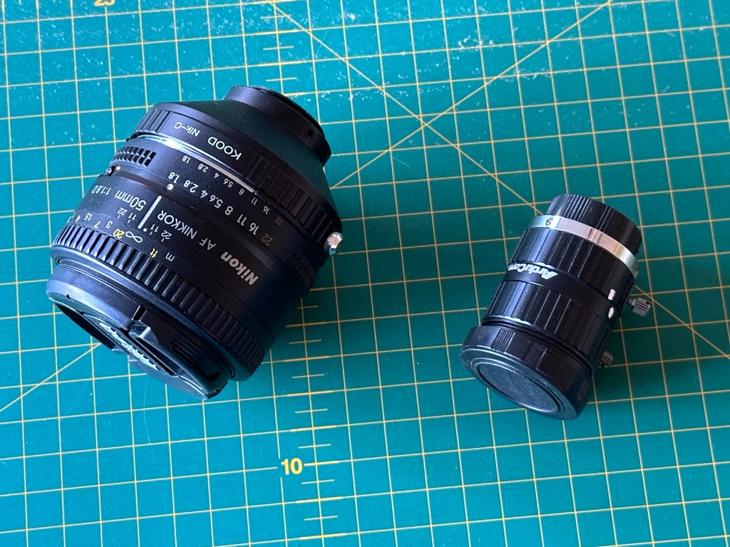
I found that by defining the problem well with copilot I could get it to write code to do the same cleaning efficiently. What was really useful is that copilot can analyse your example images. I described the camera sensor and lens I was using, including that the IR CUTOFF filter was removed. Copilot then made some reasonable analysis of the images and what issues they could have. It then made some efficient OpenCV/Numpy routines to clean the images. This is still an iterative loop but opened a whole new way to solve future image handling problems. Once more I feel confident to try this approach because I can test input/output to see if I get the results I expect.
I have witnessed some truly weird bits of code being generated, so it’s critical that you understand what you are asking for, take time to explain it clearly to the AI, and definitely deeply study the suggested solution. Even if the result is wrong, sometimes you still learn new things though!
Utilities added
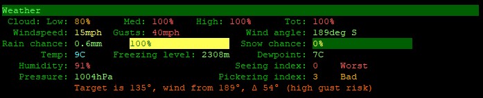
METCHECK.COM weather forecast
When planning observations it’s useful to know if the conditions will be right.
Here on the UK coast of the North Sea we don’t get many perfect nights so you don’t want to miss them when they come. There are lots of websites and phone apps for the weather, I use a few of those to plan the week ahead. When the actual night of observing comes I switch to a live data feed from https://www.metcheck.com/BUSINESS/developers.asp
For my location I have found this weather data feed really useful and generally accurate. METCHECK.COM make a weather forecast available for any latitude/longitude on Earth. You can download this as a json file from their website. The file is large and difficult to read in the raw json format so I made a terminal interface to show the information in a table. I have included this utility program now in the github repository for the project.
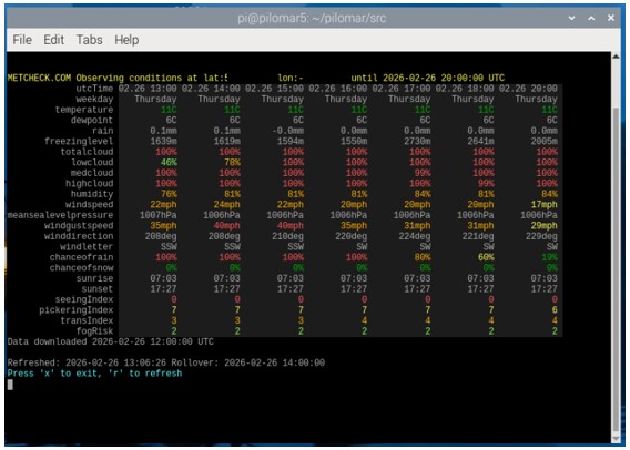
You can open a terminal window, go to the src directory and enter
python pilomarmetcheck.py
This command will display a table of colorcoded weather forecast information.
Each row is a different weather measurement. Each column is a time into the future. The wider your terminal window, the more columns can be shown.
The utility refreshes automatically every few minutes to keep the information up-to-date. The same source code src/pilomarmetcheck.py provides the class metcheck_handler() which you can use in other programs if needed.
from pilomarmetcheck import metcheck_handler
Check in src/pilomarmetcheck.py to see how it is used to extract and display the data. The metcheck_handler class is also included in the pending version of src/pilomar.py so that weather conditions can be monitored and also recorded in image metadata.
NOAA Aurora conditions
I hate to miss an aurora display, we’ve had some very spectacular displays during the current solar maximum but our notoriously cloudy nights mean it’s difficult to actually catch them. I noticed that all the online aurora visibility maps show the data from NOAA.GOV of the ‘ovation data‘.
This is a map of the likely intensity in the next 30 minutes for each lat/lon on Earth. If I understand correctly this is the ‘probability’ of seeing the Aurora directly overhead. But the aurora is usually 100km high in the atmosphere, so even if it is not directly overhead you may still be able to see it overhead a nearby location.
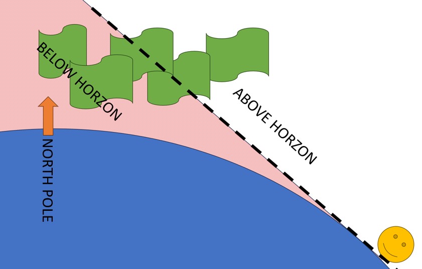
So I wrote a ‘projection’ routine which estimates what the aurora may look like when viewing it from a distance. It is a simple terminal interface which refreshes automatically every 15 minutes. It shows the aurora oval as you might see it yourself. You can see the size of the oval and whether it is above or below
the horizon from your location.
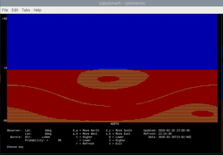
In this case, no, I probably cannot see it 🙂
The online alerts are still the best way to START looking for the aurora, but if you have an alert ongoing I use this tool to monitor the movement and latitude of the aurora during the event. It relies entirely upon the probability calculate by NOAA, and there are many other issues that can affect your view of the
aurora, but it was an interesting challenge to program given my poor mathematical skills!
To run it go to the /src directory and enter
python pilomarovation.py
The same source code src/pilomarovation.py provides the class pilomarovation() which you can use in other programs if needed.
from pilomarovation import pilomarovation
Check in src/pilomarovation.py to see how it is used to extract and display the data.
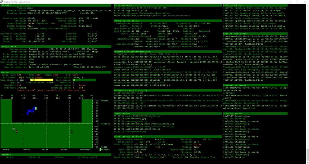
Checking images on a terminal
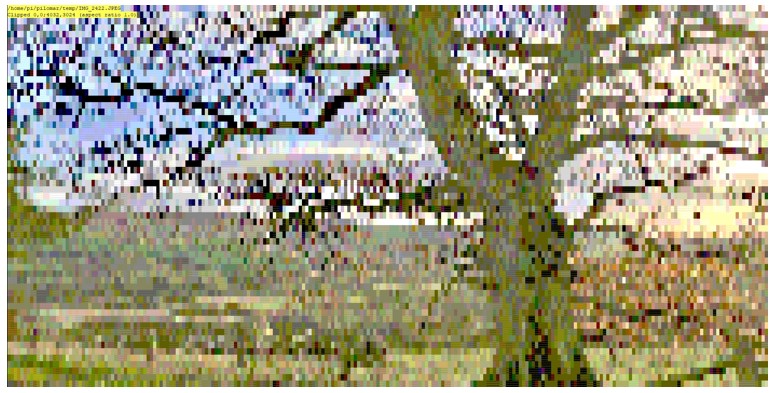
Here’s a crazy one. I’ve developed the project as a character based application. But it’s really useful to be able to see images as they are being captured sometimes. Normally I use SFTP to transfer the .jpg files off the RPi and onto a PC for viewing. This is great, but sometimes I just need a very quick view of an image. I added a utility to display .jpg files through the terminal interface. It uses the XTERM 256 color palette to display a downscaled copy of the image.
I’ve found this strangely useful! So I’ve included it in the project repository now too.
To run it go to the /src directory and enter
python pilomarviewer.py '[filepath]'
where ‘[filepath]’ is a .jpg filename or even a wildcard filepath. The ‘quote marks’ are important if you use wildcards.
It displays the image in the40x160 terminal window. You can pan/zoom around the image as you need. If the image gets updated on disc the display automatically refreshes. If you enter a wildcard in the filepath such as ‘/data/light_.jpg’ it displays the most recent matching image.
You will be able to launch this from the next pilomar.py program too and link it to the current observation automatically.
Observations
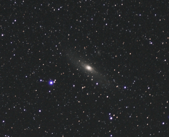
2025 was a terrible year for observations here, the summer was fantastic, but up here too light at night. The winters too cloudy. We have had maybe 3 good viewing nights so far this winter and 2 of them had a bright moon to complicate things. But I managed one night recently where I could test everything nicely for a few hours, and the whole package still works, actually when it works really smoothly you have to find a good book to read.
We’ve missed a few spectacular aurora displays due to weather, but sometimes caught a glimpse when the cloud has broken up. I still want to play with the ‘keogram‘ function in the pilomar software on a good aurora display.
Next steps
When the new release is ‘stable’ I will return to the plate solving problem. I’m determined to get a solution up and running for this, and I think that the AI tools will probably speed up the development for me now.
I’m in the process of updating the Github repository for the project with the last 10 months of developments and changes, hope to have all that published soon including the latest TMC2209 PCB design.
Spring is approaching so already my mind is turning back to more summer development tasks. I hope that some of the other builds around the world are in better climates and getting some good images back!