February 2024 update

Instructables builds

There are 5 ‘I made this’ posts on Instructables now for pi-lomar, and a few other builders have been in contact with questions and suggestions over the last two months. I’m really looking forward to seeing what people manage to do with the telescope and get some feedback and improvement ideas.

GitHub for pi-lomar updated

The January issues branch in GitHub became quite a monster, there is a list of all the changes available here. I’ll cover a few of the interesting items here.

UART communication problems

A few people have had problems getting the communication to work between the RPi and the Tiny2040. This has been due to a few different issues, but it became clear that more help was needed to identify where the problems are when communication doesn’t work. If something is wrong in the communication chain you might get an error message, or you might simply get a ‘dead telescope’ which refuses to move. So I’ve added features to detect and complain more clearly if something is wrong, and also a way to monitor and test the communication in realtime.

Software versions

The original build required very specific versions of CircuitPython and the Raspberry Pi O/S. I’ve addressed a few of the limitations now so you can use the most recent copies of both. I’ve now got a telescope running happily with Bookworm 64bit on an RPi4 and CircuitPython 8.2 on the microcontroller. This means you can use whatever the current version is – you don’t have to go looking for archived copies anymore. The released version does not work on the RPi5 yet – I’m going to rework the camera handling for that beast first.

Motor configurations

The original design was heavily dependent upon specific stepper motor designs. This was quite restricting for some because they are not always easy or cheap to source. The new software has moved the motor and gearing configuration into the parameter file instead of being hardcoded. So now it is simpler to set up alternative motors AND you can still take updates to the software without having to repeat your own hardcoding changes.

Removing the infrared filter

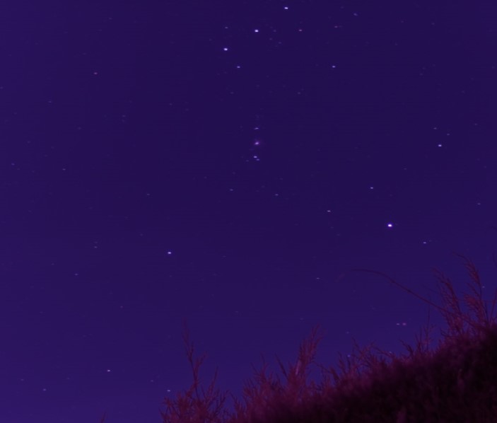
In the last blog I mentioned that I had removed the infrared cutoff filter from one of the camera sensors. I had to wait a while for a clear enough night, but eventually grabbed a few shots of the region around the Orion Nebula. It was not a great observing night, there was considerable haze and some random cloud, but I got a few images.

I am happy to confirm that it really made a difference though. New objects appeared and previously faint objects are clearly enhanced by expanding the vision of the sensor.

After stacking and some enhancement in The GIMP, this is the region with the new infrared capability. I was not able to remove ALL the haze, but if you are patient you can reduce it considerably.

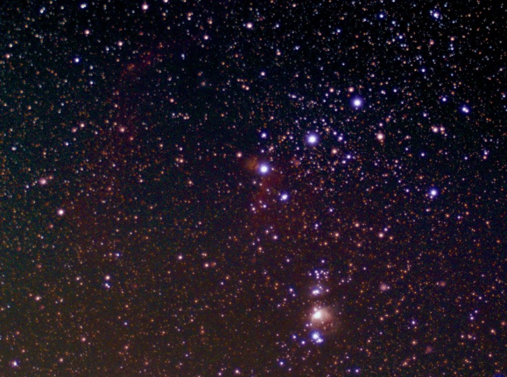
For clarity I’ve marked the major items that are now visible below.

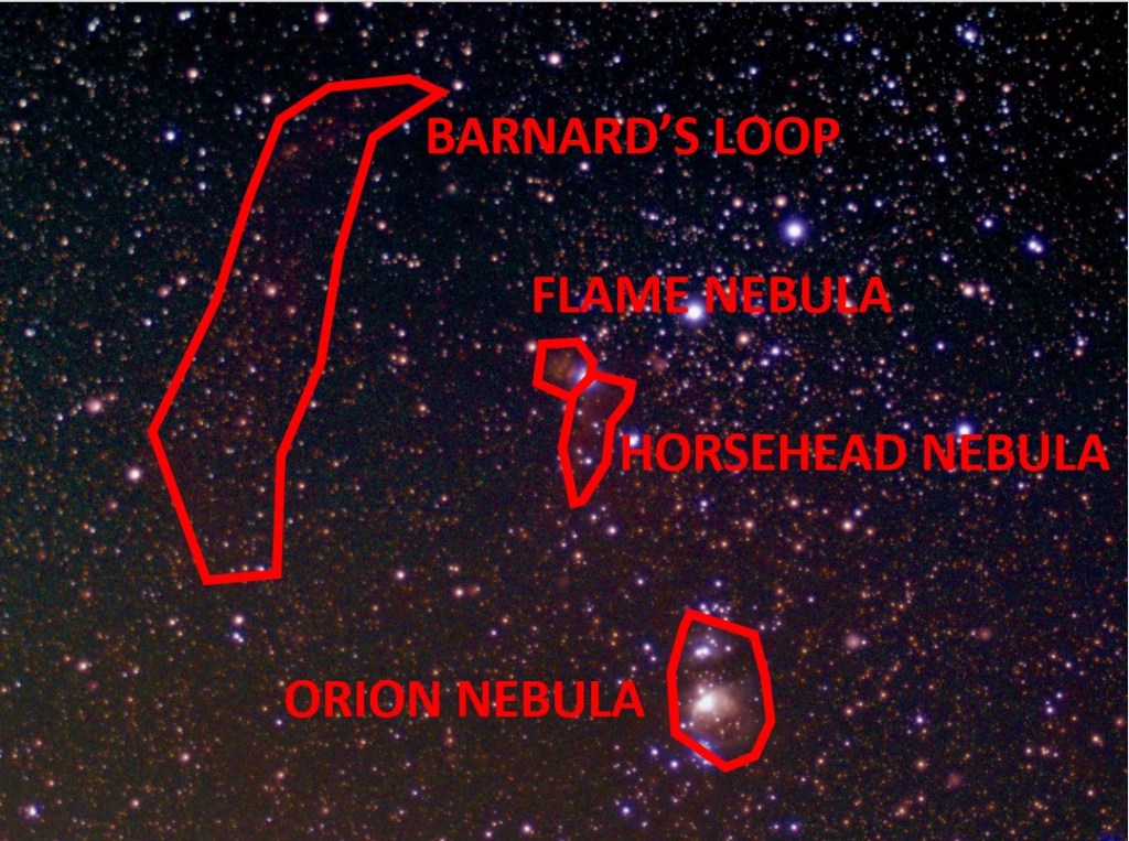
There is clearly a colour tint still to these images which I need to play with some more, but there are definitely new details here.
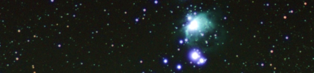
Orion Nebula

There seems to be a larger area of nebula visible in this image. The colour variation is not as good as earlier images but I think that’s something I can still work on.

Flame Nebula

This was faintly visible before the infrared cutoff filter was removed, but it seems to be more clear now. Hopefully when I can gather more images to stack I can pull more clarity from that still.

Horsehead Nebula

With the infrared filter in place you could see a very faint hint of the Horsehead Nebula surroundings, but they were very subtle. You had to know there was something there and then play with image enhancement to get even a slight hint of it. But it is now more clear.

Barnard’s Loop

Orion is surrounded by a large ‘infrared only’ area of gas. I’ve never seen this before in any observations I’ve made, but suddenly it’s there. Barnard’s Loop is to the left of the belt, and although faint, there’s no doubt it’s now detected. The gas cloud extends lower down around Orion too, but in this shot it’s hard to separate urban haze from actual gas cloud.

Urban Haze

This brings me to by current problems, urban haze. There is light pollution and generally poor quality atmosphere around here. I’m not living in a big city but the conditions are visibly deteriorating as time goes by.

The IR image above is taken with the 16mm lens, I have now removed the IR cutoff filter from the 2nd telescope with the 50mm lens too. That also has a light pollution filter added. The brief chance I’ve had to test it suggests that it does indeed make a difference to the haze that’s creeping into all the shots. The question is- does it also reduce the infrared wavelengths too? The next clear moonless night may answer that.

There’s another place where haze becomes an issue. That’s in the drift tracking mechanism of the telescope. Pi-lomar checks its position by taking a live image and comparing it with a calculated image of the sky. It uses the difference between star locations to correct the position of the camera. It’s not perfect, but it works well enough for the images to be stackable. But if there is strong haze in the sky the Astroalign package can struggle to recognise and match stars between the images. You can get a cloud of false stars at the bottom of an image which confuses things.

To work around that I use OpenCV to try to enhance the stars in the live tracking image. Basically trying to reduce noise and enhance just the real stars. This requires tuning some OpenCV filter functions to work nicely with MY particular observing conditions. That’s a problem for people in other locations, they may need to tune the filter functions differently.

So I’ve modified the software to make these OpenCV filter functions into ‘scripts’. You nolonger have to play with hardcoded function calls in the software, you can simply edit the scripts and test them rapidly against your conditions. I hope this is a good benefit for people. I will probably refine the configuration and testing further in future versions. This is clearly an area where a graphical interface would help. An early test of this new feature looks promising when trying to filter out tree branches from someone’s live tracking images. It looks like we can still pull stars out of quite busy and noisy shots.

Next steps

I am not intending to develop the software further now until the summer. The latest update needs to be taken into use and tested in more environments, so I want to limit any new changes to bug fixes or tuning related to that. Spring is approaching, it’s better to spend time observing!

January 2024 update

Testing Pi-lomar on the Raspberry Pi 5

Will Pi-lomar run on a Raspberry Pi 5?

Spoiler alert! No.

Not yet.

The camera and GPIO libraries have changed, but how close is it to working?

Interestingly more of the required packages that made the RPi 4 Buster build tricky seem to be pre-installed in Bookworm now. I only added opencv, astroalign, pandas and skyfield, and they all installed cleanly, no conflicts or special tricks needed.

sudo apt install python3-skyfield
sudo apt install python3-opencv
sudo apt install python3-astroalign
sudo apt install python3-pandas

The resulting build script will be much simpler I hope. I’m still installing globally rather than creating containers because the RPi will be dedicated to the telescope.

The pilomar.py program of course errored out fairly quickly, but with relatively little change I got it up and running as far as the first menu. That includes all the data loading and formatting that has to happen when you first run the software.

Right out of the box I have to say “wow!“, I’m impressed.

For comparison: The 2GB RPi 4B with the 32bit operating system takes about an hour to calculate the Hipparcos catalogue of 100000+ stars. On an 8GB RPi 5B with 64bit operating system, it ran in 25 seconds, so fast that I thought it had failed, I had to speed up the progress messages to prove it was doing something. From nearly 60 minutes down to 25 seconds! In regular use I’d estimate Pi-lomar runs about twice as fast on the RPi5.

It looks like the basic migration should be straight forward, and there is capacity there for extra features.

Raspberry Pi 5 Active Cooling hint!

The official cooling unit is great – it’s very easy to attach to the RPi5. BUT – you can’t detach it. So, if you’re thinking of later putting it into a case or occasionally reorganize things, be very careful.

For example: I like the Pibow cases, but a couple of design choices clash. If you connect RPi+Cooler first: You cannot fit all the layers of the case.
If you connect RPi+Cooler second: You cannot remove all the layers of the case, and the camera connectors become more difficult to access.

Next time I’ll change the little spring-loaded feet for nylon bolts so the cooler can be removed – that’s the fundamental design flaw to me.


Back to the RPi 4B version

Motorcontroller PCB

The published PCB as it arrives from a manufacturer. No components, you have to add those yourself.
Unpopulated PCB as received from the manufacturer.

The first PCB design is done and the Gerber files are now in the GitHub project for the PCB. These files can be used to manufacture the PCB. It still needs to have components added, but the wiring is all set in the PCB itself. Many thanks to Dale, Mark, and Ton for their help with the designs so far.

The published PCB has a few improvements on it.

  • Full ground plane on the underside of the PCB.
  • 12V supplies have more copper too.
  • The unused ADC0 pin on the Tiny2040 is now available in the expansion section for your own use.
  • A number of GPIO pins from the RPi header are now exposed in the expansion section.
  • Some development features (LED and motor power measurement) are removed.
  • PCB connector blocks have been standardised.
  • Printed warning to take care when connecting USB and GPIO at the same time.
  • NOTE: On the published Gerber files, the ‘R1’ resistor is marked with a lower value than these images show. Any value from 320 – 680 Ohms seems to work fine. The lower the value, the better the transistor switches.
Published motorcontroller PCB with components populated.
Populated at home with the necessary components.

I have added a new folder to the GitHub project to contain the Gerber files.

https://github.com/Short-bus/pilomar/tree/main/gerber

The files for the PCB are in the /gerber/PCB-2023-12-14 folder on GitHub. You must generate a .zip file from here to use for manufacturing.

cd gerber/PCB-2023-12-14
zip PCB-2023-12-14.zip *

The PCB-2023-12-14.zip file is the one that you should submit for manufacturing.

The file gerber/readme.txt explains more about the manufacturing specifications you will need to provide when placing an order.

A second PCB design is still in testing at the moment, this one eliminates the separate Raspberry Pi power supply. It adds a buck converter onto the board to act as the RPi’s power source. Everything runs from the motor 12V supply.

Software development

At the end of December I released a few improvements to the software, fixing a few issues that the early builders found. I think people should be taking their first images soon, so I’ve done a little more development in January to help tuning the telescope.

The tracking algorithm works for me, but I suspect that it needs finetuning to individual observing conditions. There are some great sounding locations where people are building Pi-lomar at the moment. So I’ve started adding some simple tools to help get the tracking parameters right. The idea is to show the results of the tracking calculation and the related parameters which can impact how it works. (I must explain how the tracking solution works soon)

Getting the telescope working south of the Equator! I am at 50+ degrees North here, out of extreme caution I put a warning on Instructables and in the software that the telescope might not work if you go too far south. But there is interest to make copies in the Southern Hemisphere. So with help from volunteers I’m looking at addressing some minor irritations with how the telescope behaves as you move further south. It looks like Pi-lomar will work already – but with a movement reset while tracking objects through due North. So the January release will accept Southern latitudes for the home location now and just warn you that it’s still under development.

There’s now a parameter “OptimiseMoves” – when you turn that parameter on the telescope will move much more freely through due North which should eliminate some irritations.

Example of the warning message that pilomar.py generates if the OptimiseMoves parameter is enabled.
Screenshot showing the warning if the new OptimiseMoves parameter is enabled. Should make smoother operation when making observations facing north more of the time.
Diagram to explain the motion differences when the OptimiseMoves parameter is used in Pi-lomar.
The effect of the OptimiseMoves parameter. By default the telescope will not pass North (360/0 degrees), it will reverse back to the other side and resume there. Enabling OptimiseMoves allows the telescope to rotate freely past North in either direction.

I’ve opened discussions on the GitHub site for anyone who wants to join in. When the feature is fully developed and proven to work that will become the normal operation everywhere.

The January improvements will be merged back into the main branch in the next few days.

Actual observations

It has been almost constantly cloudy here for months now. And the back yard is turning to mud, even the dog is reluctant to go out there. Really frustrating! I’m SO desperate to get out and get some more images captured. Nights on the east coast seem to come in three flavours…

  1. Too cloudy, calm, no moon.
  2. Clear, too windy, no moon.
  3. Clear, calm, full moon.

I’m hoping that some of the other builders will start capturing soon, maybe people can share those images too.


Hardware developments

Upgrading mk1

I have two completed Pi-lomar telescopes at the moment. After a break from 3D printing, I’m returning to the earlier build to upgrade it. The drive mechanism now feel less smooth than the Instructables version. That’s a relief! All the tweaks I put into the Instructables version made a difference. So I’ll be tearing mk1 down and testing out some further improvements to the drive and telescope tower. I’ll take the opportunity to widen the camera cradle – it will allow more room for higher quality lenses, and also let me test out the idea of an RPi5 with twin cameras later this year.

Prototype 3d printed part. This is a twin camera cradle idea. When connected to a Raspberry Pi 5 the telescope could support 2 cameras, each one optimised for different purposes.
First version of twin camera cradle. This will need a RPi5, but could run a 16mm lens for targeting/tracking and a separate 50mm lens for observations. (I hope!)
3D printer underway. Printing a new version of the tower walls to make more space inside the dome for more and larger lenses.
Modified design for tower walls under way to make space for the twin camera cradle.

Removing the infrared filter

Finally time to rip that infrared cut-off filter out of a Hi Quality sensor. The official instructions work, it is simple to do. The lens mount comes off the sensor board easily and the IR filter pops out cleanly with gentle push. I have left the sensor exposed, protected only when a lens is attached. I may try to re-cover it with OHP film as suggested as exposed sensors are dust magnets! I put the sensor inside a fresh clean freezer bag to minimise dust when making the mod.

I placed the 16mm telephoto lens on the sensor and stuck it on a tripod just to see what things looked like. Everything has now gone ‘pink’ so SOMETHING has changed anyway!

A very quickly captured image of the sword of Orion. Just moments after removing the infrared filter from a Raspberry Pi Hi Quality sensor. The sky has turned pink, so there is definitely a change in the wavelengths being captured. Just waiting for less moon and less wind to test it properly.
Infra red filter removed from Raspberry Pi Hi Quality sensor. Tripod mounted photo of Orion’s sword with 16mm telephoto lens and moonlit sky. It’s all gone PINK, that must be good right?!?

It’s not clear how wide the HiQ sensor’s infrared sensitivity is, but I think any expansion of wavelengths will be interesting to play with.

Fiddly focusing

I had to refocus the lens when I reattached it, and realised a better way to get it in focus. The focus ring of the 16mm lens is not very precise compared with larger lenses, I’ve always struggled a bit with this. I tried a different approach this time.

I set the lens focus ring fully to ‘FAR’ and locked it off. Then released the screw clamping the sensor mounted rear focus ring. That’s a much finer screw thread, it has a more positive movement, and allows really fine focus adjustment. It is mentioned in the official instructions, but I think it’s the BEST way to focus if you’re being fussy.

With this, the ‘raspistill –focus‘ command trick and some patience you can get quite fine control over the focus. You DO need a monitor connected via the HDMI port though. The preview image does not appear through VNC or puTTY sessions.

As always, it’s best to close the aperture ring a little to increase depth of field. I always reduce it to F2.8 so it’s still bright, you can reduce further if you are having problems.

Light pollution

We sit just outside an expanding town which is switching to LED streetlighting. Light pollution is an increasing problem. I have purchased a simple ‘light pollution‘ filter to add to the 50mm Nikkor lens. I will be testing this as conditions allow, I wonder if it helps, and I hope it doesn’t block infrared!


Other builds

As mentioned earlier, quite a few makes are now underway with the Instructables project. The first ‘I made this‘ post has appeared (well done Jeff!), and from the messages I have seen there are a few nearing completion.

It looks like the most common pain points have been the PCB (see above) and sourcing the motors and worm gear components. Hopefully PCB sourcing is easier now with the published Gerber files. I saw a couple of cases where people shared a PCB order to reduce costs.

For the worm gear, I wonder if a future design could switch to using planetary gearboxes on the Nema17 motors instead. They seem to be more widely available, and can even be purchased as complete units. They may require a rethink of the drive mechanism, I have ideas already.

At least one builder is improving the weatherproofing of the design, that will be exciting to see when it is ready. I think there is a lot to learn from that development if it happens.

There are a couple of really interesting alternative motor controller designs out there too, including alternative ways to power/reset the Tiny2040 as well.


Off the shelf motorcontrollers

I mentioned in December that I haven’t found a suitable off-the-shelf motor controller board yet. Well, in the tech world, a month is a long time. I recently came across an announcement from Pimoroni about their new YUKON board. The specifications sound interesting. It supports high current stepper motor drivers, has a modular design and an onboard RP2040. There’s a fully featured builders kit available, but you can also buy the bare board and individual driver components. Pimoroni’s website has a couple of overview videos, and there’s an example robot project on Youtube by Kevin McAleer. I’d like to try one of these at some point, IF I find the time. Maybe someone else will give it a try?

Pimoroni's image of their new Yukon robotics board. The specification sounds really useful for telescope control too.
Pimoroni’s website image of their Yukon board. Haven’t tested it yet, but the specification sounds really useful for controlling the telescope motors without having to build your own PCB.

So, quite a bit to test now. Here’s hoping for some clear, calm, dark skies before the winter is over!